![]()
I have a youtube channel with over 1000 Videos!
![]()
![]()
![]()

Hi, Thanks for visiting my website. My name is Will and if you have questions
or would like to
contribute projects or ideas you can contact me 
![]()
I have a youtube channel with over 1000 Videos!
![]()
![]()
![]()
Hi, Thanks for visiting my website. My name is Will and if you have questions
or would like to
contribute projects or ideas you can contact me
This is a continuation of my project on making an ARF Model Airplane. You can start at page one of this series here. In this part of the series I will go over more of the assembly of the plane. But not completely. We will take a look at mounting the control horns and the servos. The fuel tank and more. And I will point out a few other things. There is a video showing a lot of this stuff at the bottom of this page.
|
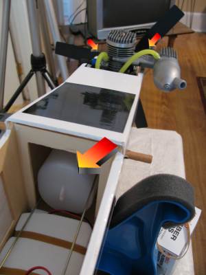
The fuel tank is pretty easy to install although there are some variations in tanks. sometimes you have to assemble the fuel tank itself before installing it. But in the case of this one all I had to do was insert the two fuel lines then slide the tank right into the front of the airplane fuselage. Run the fuel lines up to the front then connect them to the carbuerator and the muffler after trimming them down to an appropriate size. Now we don't have to access the fuel tank. We fill and empty it through one of the lines.
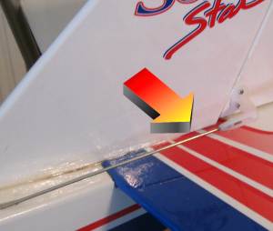
This picture shows the installed control horns on the rudder and elevator which is the back of the plane. These white plastic horns are connected by a linkage to the servos. When the servo moves it moves the linkage and this moves the rudder or elevator. You drill 1/8 inch holes then use small screws to affix them to the plane.
This picture shows the control rod (linkage) connected to the control horn.
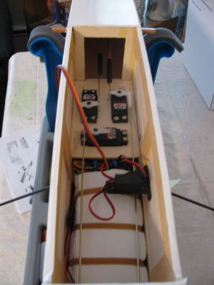
This picture shows the linkages inside the airplane. You can see four different rods. Two of them go forward in the picture, this is toward the rear of the plane and these connect to the rudder and elevator we looked at in the previous two pictures. The other two control rodes (longer and coming toward us in the picture. Go to the front of the plane. One of them operates the throttle and one of them operates the turning of the front wheel. Okay, Now is a good time to take a quick look at those servos that I have talked about. These are the real heart and soul of the RC airplane. They are how the plane is operated.
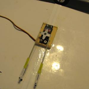
And this picture gives us a good idea about the whole concept of the servo. This servo (black with the white four pointed star on it) is inserted into the wooden servo tray and is right in the center of the dihedral wing. The two rods are connected each to an aileron on the wing. So, when the white star turns the rod moves and the aileron is forced up or down. This may be a bit confusing because of the two rods. But what happens with this is that when the servo rotates a little bit one way it causes a push on one rod and a pull on the other rod. So, one aileron is pushed up and the other aileron is pulled down.
So let's take one more look at those three servos inside the body of the plane. These are screwed into the servo tray that we installed earlier and hooked up to their control rods. And they are connected to the receiver of the plane which is currrently tucked under the white object with rubber bands on it. The battery that powers the servos is also tucked under there. So, When the receiver inside here gets a signal from the handheld device you are controlling it sends a message to the appropriate servo, telling it to turn a bit and activate the control rod.
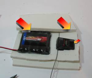
Now let's take a look at that battery pack. Now that we have installed all the servos and the linkages we are ready to create and install the battery/receiver pack. This picture here shows it. It is simply several sheets of foam with the components embedded into it. The battery pack is on the left. This gives power to the receiver and gives power to the servos when the receiver tells it to. The battery pack is plugged into the receiver and when you send the receiver a signal the receiver passes some power through to the servo. All the servos get connected to the reciever at the spot shown with the smallest arrow.
So we connect the battery to the receiver and we connect all the servos to the receiver and we are just about done with this airplane. Except for placing the wings and installing an on off switch we only have one more thing to do and that is to install the engine. But let's take a quick look at the on off switch.
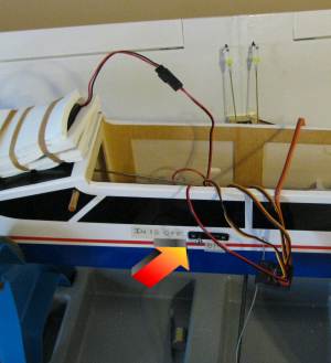
To install the power switch you cut a small rectangular hole in the left side of the airplane. It is important to do it on this side which is away from the exhaust of the airplane. And simply screw the switch in then connect it. In this picture I have actually installed a dual purpose switch. It turns the power on and off and it also has a neat little charging port so the battery can be charged without taking off the wings. If you are building an airplane you might want to consider getting a dual purpose swithc like this because normally after every flight you would have to take the wings off and get at the battery pack so you can charge it. With this all you have to do is plug the charger right into the socket here on the outside. Much easier and worth the extra dollar spent.
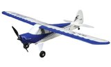
The HobbyZone Sports Cub S RC Airplane
|