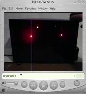
The Firefly Diorama View the Quicktime Movie
About This Diorama
I got an email from a visitor to this site who was looking for advice on how to make a nice Firefly Diorama and I thought to myself "What a wonderful idea"! Because I could use some tiny blinking LED's as fireflies. It takes a bit of electronics skill to do this project but it comes out really wonderful.
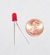
LED's are tiny Light Emitting Diodes. This is a picture of one of the LED's I used for this project. It is rather small but it really emits a strong light. This is exactly what is used on many electronic devices like tv's, and stereo's. If you have an electronic device that has a little red, yellow, green or other color light on it that is an LED. The type I used for this diorama is a blinking style. If you apply to it the voltage from a battery it will automatically blink and in a random pattern so all the LED's (fireflies) I have in my diorama blink randomly which makes it really nice.
About the Electronics and the Wiring
Parts List for this Shoebox Diorama Project
- 1 Shoebox
- 4 AA batteries
- 1 battery holder (From Radio Shack)
- 5 LED's
- About 10 feet of thin wire similar to telephone wire. Approximately 24 gauge if you know wires and electronics. 5 feet of red and 5 feet of black I used telephone wire, stripped off the sheating and used the black and red wires inside it.
- 5 resistors (1 for each led) and the value can be almost anything from 5 ohms to probably 100 ohms or more, I used resistors with a 5 ohm value.
- a little switch to turn the fireflies on and off (I used a pushbutton so it is only on as long as you push the button down.
About the resistors and the LED's
LED's are rather sensitive to the current that flows through them and if you connect a battery directly to them you will ruin them. So you really need to attach resistors to each one in order to keep them controlled and operating.
If you are going to do this project I recommend you get extra LED's and a few different value resistors so you can experiment a bit before you actually wire them into your shoebox diorama.
The Wiring Diagram
\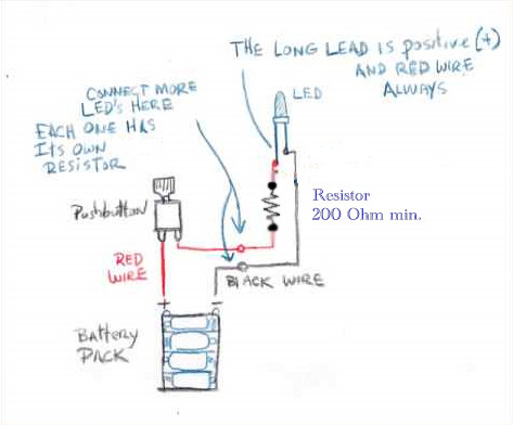
About the wiring for the diorama- It is pretty straight forward with a battery pack, a pushbutton, LED, resistor and some wires.
Update on this wiring diagram: I got a terrific and very helpful email from Grenathor who re-designed this circuit to make it much more efficient. The diagram above is the re-done circuit and here is what he has to say:
How it should be connected:
The resistor has to be connected in series with the LED. By doing this, you limit the current that will flow through the resistor to the LED. By varying the resistor, you will be able to vary the LED's intensity, making it brighter or darker. A standard LED needs about 25mA to work ( 0.025 Ampere ). Currents higher that 50mA will shorten the LED's life, and even higher currents will simply fry it. Currents under 5mA will make the LED too dim. The resistor will only let a certain current get through to the LED. There's a bit of math if you want to calculate the exact value of the resistors, but you can always experiment. As a general rule, on a 9V battery, using a resistor lower than 200 Ohms will damage the LED. You can use resistors as high as you want, but using resistors higher than 5000 Ohms will be too dim. The lower the resistor, the higher the current, the brighter the LED. You can still connect multiple LED's in parallel on the battery, but each LED needs its own resistor in series with it.
Important thing to note is that the LED is very sensitive to polarity. The LONG LEAD on the LED is the Positive (+) and must be hooked up to the positive of the battery pack. If you hook this up backwards it will ruin the LED. This is why I used red and black wires. All the red wires are the positive wires.
Once you have all the wiring done you just have to install everything. I poked small holes in the back of the shoebox and inserted the LED's
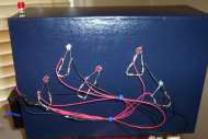
Then I used electrical tape over everything to cover the wiring. This image shows the wiring before the tape covering.
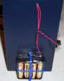
This is the battery pack for the diorama. I bought it at Radio Shack for two dollars. I put four "AA" Batteries in it. Then tied it to the side of the shoebox diorama.
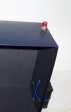
I punched a little hole in the top of the shoebox and inserted the pushbutton.
Want to Make your own Flasher circuit without buying the Flashing style LED's. Or do you have regular LED's and want to make a circuit so they flash?
Grenathor has added a terrific little wiring diagram on how to do this:
Here are his notes about this circuit:
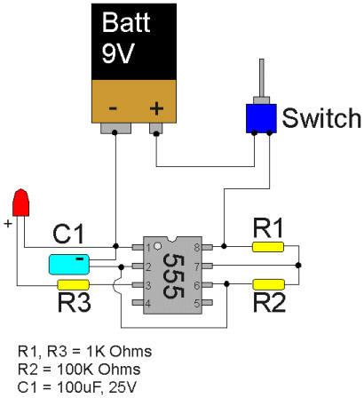
Here's the LED Flasher circuit. It's build using common electronic parts found at radio shack. You will need a 555 timer chip, 3 resistors, 1 capacitor, a LED, a switch and a 9V battery. You can also use a 6V battery pack, the 555 chip works from 5V to 15V. You will need some soldering skills to solder the electronic parts on the chip pins, make sure not to solder two pins together. It can be done without using a printed circuit board. Like the LED, the capacitor is a "polarized" component, make sure the negative pin of the capacitor (marked with a - on the side of it) is connected to pin #1. The 555 chip also has a notch or a dot engraved on it to identify pin #1.
The values I noted on the picture will give you a cycle of about 10 seconds, LED on for 5 secs, LED off for 5 secs. Using a different capacitor will change the blink rate. A 10uF capacitor will blink every second, a 1000uF capacitor will have a 100 secs cycle, always at a 50% on/off ratio. Capacitors are rated on their voltage also, make sure you use a higher voltage rating than the voltage of your battery.
Changing the value of R3 will change LED brightness. Like the other circuit, don't use a resistor under 200 Ohms to drive your LED. The 555 can sustain a load of about 200mA, which means it can drive about 5 or 6 LEDs on its output. You can add other LEDs, each LED with its own resistor, on pin 1 (-) and pin 3 (+) of the chip. Check the polarity of your LED as well, but don't worry, connecting a LED backwards will not damage it at this low voltage, it simply doesn't work.
R1 and R2 should not be changed, unless you understand how the chip works in depth. It's easier to just use these resistor values and change the capacitor value.
BTW I'm not sure if you already know this, 1K Ohms = 1000 Ohms, 100K Ohms = 100,000 Ohms.
Capacitors are rated in Farads (F), but capacitors always have very small values, 1 uF (micro-Farads) = 0.000001 Farad
If you want to make something that works for a long time, you can use one of these universal power supplies sold at radio shack instead of a battery, just set it at 6 or 9V, check the polarity of the power supply with a voltmeter and there you go.
One thing I like to do when free-forming electronic circuits (not using a circuit board), when i'm happy with the circuit results and that nothing needs to be changed, I dip the whole circuit in hot glue. By covering all the metallic parts with hot glue, it prevents accidental short-circuits that could occur if the circuit went in contact with a metallic object.
The 555 is a small integrated circuit often called a 555 Timer IC. You can get these for around a dollar at radio shack. They even have them on Amazon.com
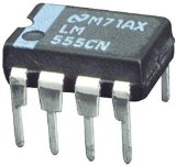

LM555 TIMER IC (8 PIN DIP)
|